The DS80C400 evaluation board
As a project at the university it was my task to build an evaluation board for the DS80C400 microcontroller from Dallas Semiconductors (now Maxim), and to employ the microcontroller's networking capabilities. The system should allow you to control devices connected to one of the board's serial ports over the Internet using TCP/IP.
As a secondary application I chose to realize an MP3 player which can play back Internet radio streams. To control this application there must be the possibility to connect an LCD and several keys to the evaluation board.
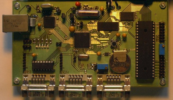
The heart of the system is a DS80C400 microcontroller, which, amongst other things, contains an Ethernet MAC, three serial ports, one CAN controller, and a 1-Wire bus master. The system contains 512 KB Flash memory and 512 KB battery buffered SRAM. The Flash is dimensioned to host a Java virtual machine, and the SRAM is big enough to be used as working memory and for the file system of the operating system.
The evaluation board has the following communication interfaces:
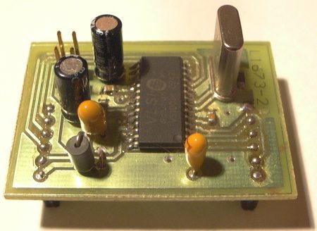
An MP3 decoder is on a second board, which fits onto the extension connectors of the main board. The MP3 decoder is a VS1001K from VLSI Solution Oy, and offers a stereo output strong enough to drive headphones.
There is a Java virtual machine and a simple operating system available for the DS80C400 microcontroller. These software components are stored in the Flash memory. The operating system has a command shell which can be accessed via a serial port or also over the network with Telnet, and there is the possibility to upload and download files using FTP. The system is programmable in Java, while time-critical code can be written in 8051-assembler, and imported into the Java project as a native library.
Please refer to the protocol (download below)
for more information, like schematics, layouts, and software.
Even though the protocol is in German the software comments
are in English.
Also feel free to contact me
if you have questions. When there is enough interest I
could translate further parts of the protocol.
The following figure shows the block diagram of the evaluation board. The individual parts of the circuit are described below.

Please refer to the protocol (download below) for the full schematics.
The microcontroller DS80C400 exposes an Intel-compatible bus, the media independent interface (MII) of its integrated Ethernet MAC, and various other signals to interface a wide range of integrated peripherals.
The microcontroller's clock generation unit is connected to a 14.75 MHz quartz. The frequency of the quartz is doubled internally, so that the processor runs at a frequency of 29.5 MHz.
There are two components on the 1-Wire bus:
The memory consists of 512 KB Flash and 512 KB SRAM. The SRAM is battery-buffered because the operating system maintains a filesystem there.
The buffering is handled by Maxim's MAX6365 voltage supervisor, which switches the supply voltage of the SRAM to a battery when the main voltage supply is interrupted. In this case the IC also keeps the SRAM's chip enable signal inactive to protect the content from unintended write operations. Further, the voltage supervisor is responsible for generating the reset signal for the microcontroller.
The Flash used is of the type AM29LV040 from AMD. The reason is that the firmware is only able to write to Flash memory from AMD, and the capacity of 512 KB is required to hold the Java-VM and the operating system.
The STE100P (subsequently called PHY) is a high performance Fast Ethernet physical layer (PHY) interface for 10Base-T and 100Base-TX applications. It provides a Media Independent Interface (MII) which is connected to the 10/100 Media Access Controller (MAC) of the microcontroller. The MII consists of two parts, the MII control interface and the MII data interface.
The circuit of the PHY is taken from the reference circuit in its datasheet. The only difference is that the used RJ45 connector (type MOL85533-0002) already contains the required transformer.
For the case that there are more PHYs connected to the MII control interface, there is the possibility to configure the address of the PHY via some pins. Because it was not clear in advance, how the firmware of the microcontroller would handle the address of the connected PHY, the address can be configured to be either 0 or 1. The Intel PHY LXT972ALC which is used in all example circuits from Dallas Semiconductors has a default address of 0, and does not even support different addresses. The STE100P, on the other hand, has the property that when it is configured to use address 0, the MII data interface is deactivated by default and must be activated by the software.
This is the reason why the NetBoot functionality of the microcontroller does not work. NetBoot expects a PHY with active MII data interface on address 0. Fortunately the Java networking code also works when the PHY is at address 1.
This protocol was part of the deliverable for this project.
It contains the circuit layouts, manuals for developers and
users, and the software source codes.
Note: Originally this document was part of a CD-ROM with
datasheets of all ICs. Out of the context of the CD there are
now broken links to these files.
Download Protocol (as PDF, 1.0 MB)