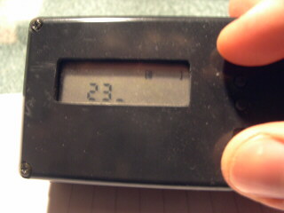
Entering the code to turn off the alarm
Our university professor for linear algebra used to threaten us poor students to call at 3 AM, to give a 100 by 100 matrix, and to ask to determine whether it was singular or not. He never called. But that kind of thing would definitely wake you up, wouldn't it?
That was when the idea was born, but not until a couple of years later I finally decided to build this alarm clock. An alarm clock that requires you to pass a test in order to stop ringing. An alarm clock that also has a couple of other features to make it more reliable than regular ones.
The following list is a collection of common shortcomings. Not all alarm clocks have all of them, but most have most.
The test to see if you are awake is simple, and many variations are possible. I implemented the following: You see five digits on the display, you memorize them, and you type them using three buttons. Only when you succeed is the alarm turned off, and to make it more interesting you only have five seconds to do this. If you fail you can try again, but you get some more of that loud ringing first...
The user interface of this alarm clock consists of three buttons, one slide switch with two positions, and one slide switch with three positions. The switch with two positions is used to turn the alarm on and off. The switch with three positions sets the operating mode to one of the following: "Normal", "Set Alarm", or "Set Time".
In the Normal state the clock displays the current time. While one of the buttons is pressed, the display shows either the remaining time to the alarm, or the temperature and battery status.
In the Set Alarm state it is possible to change the following settings:
Pressing one button circulates through these configuration pages, while the other two buttons change the respective value.
In the Set Time state it is possible to change the following settings:
Once the alarm goes off, the configuration is frozen to make it impossible to find a way to turn off the alarm other than by passing the test. This state diagram shows how the alarm is handled:

When the test is started, the clock presents a sequence of five digits from 1 to 3. The three corresponding buttons on the front of the clock must then be pressed in the same sequence. After the first button is pressed, the original sequence is hidden. For the whole procedure the user has five seconds and a progress bar on the display gives feedback on the remaining time.
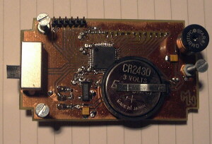
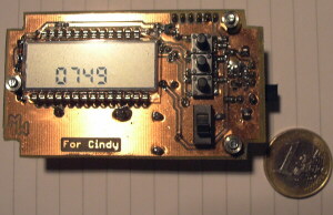
The hardware of this alarm clock is probably pretty similar to the hardware of any other digital alarm clock. You find a microcontroller, an LCD, a watch crystal, a beeper, a couple of switches and buttons, and a battery. A difference may be that the microcontroller I used is actually pretty sophisticated and could be used for much more complicated tasks. Also the LCD is not entirely suited for an alarm clock, but that's what you get when you want to order only one or two units of something.
The microcontroller I chose is the MSP430F425 from
Texas Instruments.
It is easy to program with the free development environment
from Texas Instruments and you get free samples of the
IC when you say that you are a student.
The MSP430 series is a series of ultra-low-power
microcontrollers for embedded applications; they run with 3V
and can be programmed using their JTAG interface with the
parallel port. With this interface it is also possible to
debug the software on the actual hardware.
There are many different versions of the MSP430 to choose from,
having different function blocks, peripherals, etc.
The MSP430F425 already includes an LCD driver and definitely
enough other I/O to implement an alarm clock. There are analog
inputs to measure the battery level, pulse width modulated
outputs for a piezo buzzer and for a possible LCD backlight, and
general purpose I/O for buttons. There is even an integrated
temperature sensor.
To find the right LCD was more difficult because I needed
a multiplexed one that can be used with only 3V.
Most of those LCDs you can also get in low quantities are
not multiplexed and intended for 5V operation.
I finally found the the SBLCDA4 at
SoftBaugh.
It's too sophisticated for the application, but a perfect
match for the microcontroller.
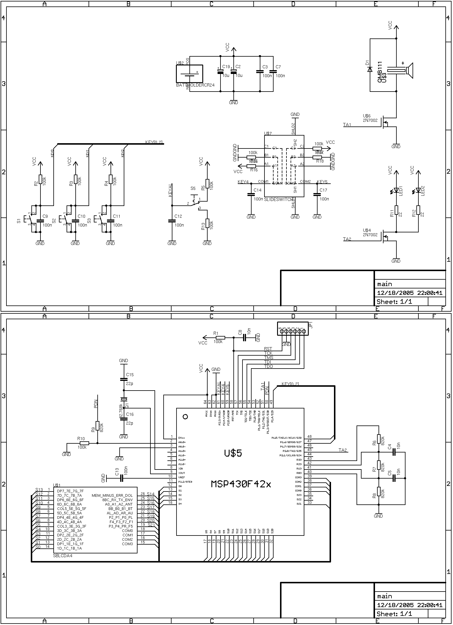
Have a look at the schematic, and in case you intend to build this thing, contact me. I can give you the files for Eagle 4.15 Light. When you have some experience, you can etch the circuit board at home without special equipment, and all parts are available in small quantities (at least in Austria).
Download or view the schematic (png-image, 26 KB)
Download the source code (zip-file, 13 KB)
This section describes the basic structure of the software running on this clock. It's just a little help to understand the source code.
Main: After initialization the main "thread" ends up in an infinite loop where it brings the microcontroller into a low-power mode. When interrupts are generated, the processor wakes up only to execute the service routine, and usually goes back into the same low-power mode immediately after. However, it is possible to tell the processor to stay awake in a service routine, which would continue the main thread. This is what the timer interrupt does once a minute so that the main thread can initiate the measurement of the battery voltage and the temperature (see below). Then the main thread goes to sleep again.
Button interrupt: This interrupt is only invoked when a button is pressed down. The event of a button being released is recognized in the timer interrupt. Buttons have to be handled with an interrupt to make sure that they are recognized even if pressed for a shorter time than the timer interval.
Timer interrupt:
The timer interrupt service routine is invoked with a frequency of
4 Hz to minimize energy consumption. Only when a button is currently
down is this frequency raised to 8 Hz to allow for finer grained control
of the button's typematic frequency.
In this service routine, the necessary button events are generated
(see below). The slide switches are queried and the state of the clock
is adjusted accordingly. The realtime clock is advanced and the display
is updated.
A/D conversion interrupt: This interrupt is invoked when conversion results of the voltage and temperature are ready. The temperature is used to calculate a compensation for the temperature dependency of the crystal frequency. When the voltage drops below a certain value, flashing of the battery symbol on the display is activated.
Handling of button-events: The three buttons have different functions in different states of the alarm clock. This is realized with a function pointer. When the clock enters a state, the pointer is set to the event handler of the new state.
Morgens aufzuwachen ist für viele Menschen ein ernstes Problem. Beim Einsatz von konventionellen Weckern kann jedoch nicht garantiert werden, dass die zu weckende Person wirklich aufwacht. Manche Wecker sind zu leise, aber alle mir bekannten Wecker lassen sich zu einfach, und daher auch im Halbschlaf, ausschalten.
In diesem Dokument wird die Idee für einen Wecker vorgestellt, der gewährleisten kann, dass der Benutzer zu einer bestimmten Zeit aufgeweckt wird. Dabei überprüft der Wecker die Geistesgegenwart der aufzuweckenden Person und hat zusätzlich einige Features, die seine Zuverlässigkeit erhöhen. Letztendlich wird ein Prototyp vorgestellt, und es werden Erfahrungen mit dessen Anwendung beschrieben.
Download Document (as PDF, 153 KB)